-
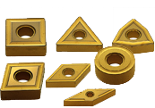
1. On a CNC lathe the most commonly used insert geometry is which?
ASquare. B80° Rhombic. CRound. -
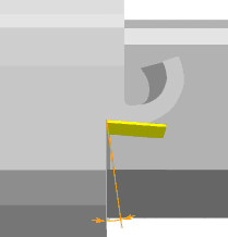
2. What is the angle shown here?
AFlank (relief) angle. BRake angle. CCutting edge angle. -

3. In the diagram shown what are the angles A and B?
ACutting edge angle and end cutting edge angle. BSide cutting edge angle and the main cutting edge angle. CSide cutting edge angle and the end cutting edge angle. -

4. Which type of clamping method is shown?
ALever lock type. BDouble clamp type. CWedge lock type. -
5. For insert geometries TNMG220408, what does the “N” represent?
AInsert tolerance. BBreaker and hole geometry. CInsert clearance. -
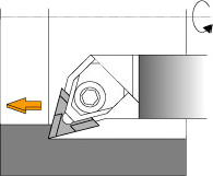
6. When carrying out boring using a ground breaker insert which is correct?
AUse right-handed boring bars with right-handed inserts. BUse right-handed boring bars with left-handed inserts. CIt does not matter what the hand of either is. -
7. One method of reducing the cutting resistance when turning is to;
AIncrease the rake angle. BDecrease the rake angle. CDecrease the cutting speed. -
8. When boring the ratio L/D refers to;
AThe length from the tool post to the tip of the boring bar divided by the boring bar diameter. BThe length of which the boring bar enters the workpiece divided by the boring bar diameter. CThe length of the boring bar divided by the boring bar diameter. -
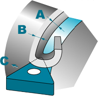
9. What text should go in the place of A, B and C?
ADepth of cut, Feed rate and Tool movement. BTool movement, Feed rate and depth of cut. CFeed rate, Depth of cut and Tool movement. -
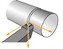
10. The 3 main forces when turning or boring are;
ABack force, Principal force and Feed force. BBack force, Principal force and Forward force. CBack force, Principal force and Side force. -
- Next
- Try again
Result